Inductor Designer Software Guide
Inductor Design Software Quick Start Guide
![]()
Inductor DesignerInductor AnalyzerProduct Finder - FAST and EASY
Inductor design is often an iterative process, where both DC and AC currents modify a material’s permeability, therefore its wound inductance. The Micrometals Inductor Designer Software automates this process to quickly provide a list of core suggestions, along with magnetic, electrical and mechanical properties calculation, based on required inductance and some of the most common drive conditions.
PFC Boost Converter

Inductor DesignerInductor AnalyzerProduct Finder - FAST and EASY
PFC inductors are characterized by having low frequency (50Hz or 60Hz typical) sine wave line current with triangular wave AC ripple at switching frequency. AC ripple varies with line current.
An active power factor correction circuit utilizes a switching circuit with an inductor in a boost configuration to shape the input current drawn by the circuit to tract the input voltage, with the goal of achieving unity power factor.
A PFC inductor is typically designed to adjust the value of power factor to make it unity. To achieve this, the effects of the load’s reactance needs to be canceled. The equal and opposite load needs to be added to the circuit to cancel the effects of the load reactance. Both capacitive and inductive effects can be canceled by using inductors and capacitors. An inductor can only cancel the capacitive effect and a capacitor can only cancel the inductive effect. There are two types of PFCs. Active PFC and passive PFC. In passive PFC, only passive electronic components like an inductor and capacitor are used.
PFC inductors are used to cancel the capacitive effects. The goal here is to make the total inductance and total capacitance equal so that the actual output power and potential power will be matched and power factor will become closer or equal to one.
This topology is commonly used for power factor correction in boost inductors.
The PFC inductance is calculated at the peak of the fundamental current at low line, taking into account any AC ripple at the peak current.
Features:
- Achieve required minimum inductance at peak of fundamental current at low line, taking into account material variation due to DC and AC ripple at peak current.
- Core and copper losses due to AC are calculated based on average over several sections of the line current with the corresponding AC ripple.
Core Characteristics:
- Good DC bias ability to maintain min inductance at peak line current.
- Low core losses at switching frequency.
- Overall high inductance throughout line current cycle to minimize overall AC ripple and corresponding AC core and copper loss.
The inductor current waveform is based on a boost converter topology operating in continuous conduction mode, which consists of a high frequency triangle wave ripple with variable amplitude superimposed on a line frequency sine wave.
The common design inputs include:
Ipk: peak of the sine wave line current.
LuH: Inductance in micro-Henry calculates as the DC biased inductance at Ipk.
Vin min: Minimum RMS line input voltage, when maximum input RMS current occurs.
Vin max: Maximum RMS line input voltage.
Vout dc: The PFC boost converter output voltage.
Fswitch: PFC boost converter switching frequency.
Ffund: The fundamental or Line input frequency.
To contact our engineering group regarding Micormetals solutions for PFC Boost Converters please use our website contact form or send an e-mail to applications@micrometals.com
DC Inductor

Inductor DesignerInductor DesignerProduct Finder - FAST and EASY
The DC inductor design is based on a DC biased inductor with a triangular wave ripple like the figure above,
typical in various offline DC-DC converter topologies.
DC energy storage inductors store energy during on cycle to release to the output during off cycle. These power inductors are used in various offline DC-DC power converters (buck, boost, buck-boost).
Features:
- Achieve required inductance at DC, taking into account material variation due to DC and AC ripple.
- Core loss calculation takes into account duty cycle.
Core Characteristics:
- Good DC bias ability to maintain inductance at DC.
- Low core losses at switching frequency.
The common design Inputs for a DC Inductor include:
Idc: Average current through the inductor in amperes;
LuH: Inductance at Idc in microhenries;
VLon: Inductor Voltage during ON time;
VLoff: Inductor Voltage during OFF time;
F: ripple frequency in hertz.
Using these inputs, our Inductor Design software will run the calculations below on a wide selection of cores and provide a comprehensive lisitng of the resulting wound designs, which can then be sorted by the most desired attribute such as core loss, cost, size, etc.
- Calculate Duty and Peak to peak current:
- Calculate number of turns, N, using an iterative process to arrive at LuH, taking into account the
- change in initial permeability due to AC ripple, using %perm vs B curve fit equation
- Calculate core loss from Bpk and F using curve fit equation.
- Calculate wire diameter, dwire, to fit turns and strands:
- For Toroid Single Layer: All strands are fitted within a single layer.
- For Toroid Full Layer: IDUsedRatio is used to calculate available window area.
- For E cores: 55% window area is used, dwire= √Awire.
- Calculate AWG from dwire based on heavy insulation, and corresponding conductor diameter, dcu, using a model, with margin to ensure fit.
- Calculate conductor mean length turn. AWG is approximate and best between AWG#5 and AWG#44.
- Calculate conductor skin depth at ripple frequency, and Racfactor.
- Calculate conductor resistance, conductor loss and temperature rise using an iterative process,
- taking into account temperature rise, in addition to ambient temperature, Racfactor, and
- Calculate core loss over time due to thermal aging.
To contact our engineering group regarding Micormetals solutions for DC Inductors please use our website contact form or send an e-mail to applications@micrometals.com
AC Inductor
Inductor DesignerInductor DesignerProduct Finder - FAST and EASY
AC Inductors are defined as operating in pure AC circuits to provide frequency-dependent impedance and are used in many filter circuits to filter high-frequency noise or for frequency selection. AC Inductors are required to handle full current without saturation and sufficient inductance and impedance at frequency or range of frequencies of concern.
AC inductors in Differential-Mode input filter provide high impedance to high frequency noise over a wide frequency range.
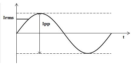
AC Inductors in resonant tuning circuit have stable inductance at intended frequency for frequency selection and waveform shaping. Their waveform is characterized as having a single frequency sine wave AC with minimal high frequency ripple.
AC Output Filters are used to filter high frequency noise from a fundamental AC current. These filters are needed in such applications as DC/AC converters and AC/AC converters such as those used on Variable Speed Motor Drives. The inductors must not saturate during the expected peak AC current, and maintain enough inductance to provide adequate filtering of the high frequency noise.
In Micrometals Inductor Design software we define an AC Inductor as a single frequency sine wave AC. This topology is most commonly used for different mode filter inductors, resonant inductors, or AC inductor with minimal ripple.
Feature:
- Inductance is calculated with modification due to AC.
Core characteristics:
- Differential Mode Filter Inductor – maintain permeability over range of noise frequencies.
- Resonant Inductor – low variation in inductance at frequency or frequencies of concern.
Distributed Gap Powder Cores are a good choice for inductors in AC Output Filters due to high Saturation and Low Cost.
To contact our engineering group regarding Micrometals solutions for AC Inductor applications please use our website contact form or send an e-mail to applications@micrometals.com
AC Inductor with Ripple
Inductor DesignerInductor DesignerProduct Finder - FAST and EASY
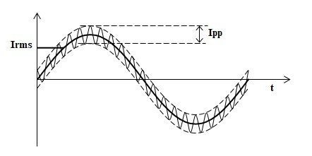
AC Inductor with ripple topology is characterized as a low frequency sine wave AC superimposed with a fixed amount of high frequency sine wave AC ripple.
AC filter inductors could see significant amount of high frequency ripple, such as at the output of switching circuit, including that of inverters and motor drives. These topologies are commonly used for Inverter inductors, Class D amplifier inductors or AC inductor with higher ripple.
The current through an output filter inductor consists of a fundamental AC Current, with some ripple current, which is the target of the filter. Micrometals distributed gap materials can keep from saturating during the peaks of the fundamental current, while maintaining excellent high frequency inductance for filtering.
Differential Mode Filters must handle the entirety of the input current, while maintaining enough inductance to provide effective filtering of the high frequency noise. Lossier materials are sometimes needed to help suppress high frequency noise. Materials -26 and -52 are most commonly employed in this application. Use "AC" or "AC+ripple" topologies in the Inductor Design Software.
For applications where it is unclear if the high frequency signal will experience the same increase in permeability as the 60 Hz signal, it is recommended that the 60 Hz signal be treated as DC current. This will produce a significantly different result but will be the most conservative approach.
To contact our engineering group regarding Micormetals solutions for AC Inductors with ripple please use our website contact form or send an e-mail to applications@micrometals.com